| United States-English |
|
|
|
Managing Serviceguard Fifteenth Edition > Chapter 3 Understanding
Serviceguard Software ComponentsHow the Network Manager Works |
|
The purpose of the network manager is to detect and recover from network card failures so that network services remain highly available to clients. In practice, this means assigning IP addresses for each package to the primary LAN interface card on the node where the package is running and monitoring the health of all interfaces, switching them when necessary.
Each node (host system) should have at least one IP address for each active network interface. This address, known as a stationary IP address, is configured in the node's /etc/rc.config.d/netconf file or in the node’s /etc/rc.config.d/netconf-ipv6 file. A stationary IP address is not transferable to another node, but may be transferable to a standby LAN interface card. The stationary IP address is not associated with packages. Stationary IP addresses are used to transmit heartbeat messages (described earlier in the section “How the Cluster Manager Works”) and other data.
In addition to the stationary IP address, you normally assign one or more unique IP addresses to each failover package. The package IP address is assigned to the primary LAN interface card by the cmmodnet command in the package control script when the package starts up. The IP addresses associated with a package are called relocatable IP addresses (also known as package IP addresses or floating IP addresses) because the addresses can actually move from one cluster node to another on the same subnet. You can use up to 200 relocatable IP addresses in a cluster, spread over as many as 150 packages. This can be a combination of IPv4 and IPv6 addresses. Because system multi-node and multi-node packages do not fail over, they do not have relocatable IP address. A relocatable IP address is like a virtual host IP address that is assigned to a package. HP recommends that you configure names for each package through DNS (Domain Name Service). A program can then use the package’s name like a host name as the input to gethostbyname(), which will return the package's relocatable IP address. Both stationary and relocatable IP addresses will switch to a standby LAN interface in the event of a LAN card failure. In addition, relocatable addresses (but not stationary addresses) can be taken over by an adoptive node on the same subnet if control of the package is transferred. This means that applications can access the package via its relocatable address without knowing which node the package currently resides on.
Both IPv4 and IPv6 address types are supported in Serviceguard. IPv4 addresses are the traditional addresses of the form n.n.n.n where n is a decimal digit between 0 and 255. IPv6 addresses have the form x:x:x:x:x:x:x:x where x is the hexadecimal value of each of eight 16-bit pieces of the 128-bit address. Only IPv4 addresses are supported as heartbeat addresses, but both IPv4 and IPv6 addresses (including various combinations) can be defined as stationary IPs in a cluster. Both IPv4 and IPv6 addresses also can be used as relocatable (package) IP addresses. When a package is started, a relocatable IP address can be added to a specified IP subnet. When the package is stopped, the relocatable IP address is deleted from the specified subnet. These functions are performed by the cmmodnet command in the package master control script (package control script for legacy packages). IP addresses are configured only on each primary network interface card; standby cards are not configured with an IP address. Multiple IPv4 addresses on the same network card must belong to the same IP subnet. It is possible for one package to have multiple services that are associated with the same IP address. If one service is moved to a new system, then the other services using the IP address will also be moved. Load sharing can be achieved by creating a package for each service and giving the package a unique IP address. This gives the administrator the ability to move selected services to less loaded systems. At regular intervals, Serviceguard polls all the network interface cards specified in the cluster configuration file. Network failures are detected within each single node in the following manner. One interface on the node is assigned to be the poller. The poller will poll the other primary and standby interfaces in the same bridged net on that node to see whether they are still healthy. Normally, the poller is a standby interface; if there are no standby interfaces in a bridged net, the primary interface is assigned the polling task. (Bridged nets are explained in “Redundant Network Components ” in Chapter 2.) The polling interface sends LAN packets to all other interfaces in the node that are on the same bridged net and receives packets back from them. Whenever a LAN driver reports an error, Serviceguard immediately declares that the card is bad and performs a local switch, if applicable. For example, when the card fails to send, Serviceguard will immediately receive an error notification and it will mark the card as down. Serviceguard Network Manager also looks at the numerical counts of packets sent and received on an interface to determine if a card is having a problem. There are two ways Serviceguard can handle the counts of packets sent and received. In the cluster configuration file, choose one of the following values for the NETWORK_FAILURE_DETECTION parameter:
A local network switch involves the detection of a local network interface failure and a failover to the local backup LAN card (also known as the standby LAN card). The backup LAN card must not have any IP addresses configured. In the case of local network switch, TCP/IP connections are not lost for Ethernet, but IEEE 802.3 connections will be lost. For IPv4, Ethernet uses the ARP protocol, and HP-UX sends out an unsolicited ARP to notify remote systems of address mapping between MAC (link level) addresses and IP level addresses. IEEE 802.3 does not have the rearp function. IPv6 uses the Neighbor Discovery Protocol (NDP) instead of ARP. The NDP protocol is used by hosts and routers to do the following:
Within the Ethernet family, local switching is supported in the following configurations:
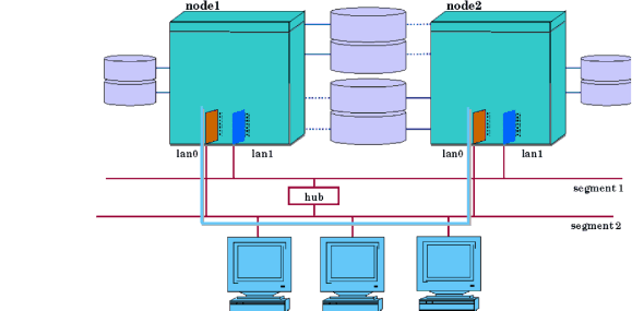
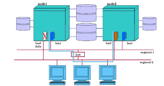
On HP-UX 11i, however, Jumbo Frames can only be used when the 1000Base-T or 1000Base-SX cards are configured. The 100Base-T and 10Base-T do not support Jumbo Frames. Additionally, network interface cards running 1000Base-T or 1000Base-SX cannot do local failover to 10BaseT. During the transfer, IP packets will be lost, but TCP (Transmission Control Protocol) will retransmit the packets. In the case of UDP (User Datagram Protocol), the packets will not be retransmitted automatically by the protocol. However, since UDP is an unreliable service, UDP applications should be prepared to handle the case of lost network packets and recover appropriately. Note that a local switchover is supported only between two LANs of the same type. For example, a local switchover between Ethernet and IPoIB interfaces is not supported, but a local switchover between 10BT Ethernet and 100BT Ethernet is supported. Figure 3-16 “Cluster Before Local Network Switching ” shows two nodes connected in one bridged net. LAN segments 1 and 2 are connected by a hub. Node 1 and Node 2 are communicating over LAN segment 2. LAN segment 1 is a standby. In Figure 3-17 “Cluster After Local Network Switching ”, we see what would happen if the LAN segment 2 network interface card on Node 1 were to fail. As the standby interface takes over, IP addresses will be switched to the hardware path associated with the standby interface. The switch is transparent at the TCP/IP level. All applications continue to run on their original nodes. During this time, IP traffic on Node 1 will be delayed as the transfer occurs. However, the TCP/IP connections will continue to be maintained and applications will continue to run. Control of the packages on Node 1 is not affected.
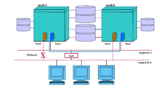
Another example of local switching is shown in Figure 3-18 “Local Switching After Cable Failure ”. In this case a failure affecting segment 2 causes both nodes to switch to the LAN cards attached to segment 1. Local network switching will work with a cluster containing one or more nodes. You may wish to design a single-node cluster in order to take advantage of this local network switching feature in situations where you need only one node and do not wish to set up a more complex cluster. If a primary interface fails, the subnet will be switched to a standby. If the primary interface is later restored, the cluster daemon will switch the subnets back to their primary interfaces. Whenever a node is halted, the cluster daemon (cmcld) will always attempt to switch any Serviceguard-configured subnets running on standby interfaces back to their primary interfaces. This is done regardless of the link state of the primary interfaces. The intent of this switchback is to preserve the original network configuration as it was before the cluster started. Switching back occurs on the specified node if a cmhaltnode command is issued or on all nodes in the cluster if a cmhaltcl command is issued. A remote switch (that is, a package switch) involves moving packages to a new system. In the most common configuration, in which all nodes are on the same subnet(s), the package IP (relocatable IP; see “Stationary and Relocatable IP Addresses ”) moves as well, and the new system must already have the subnet configured and working properly, otherwise the packages will not be started.
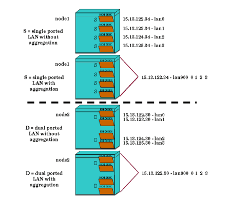
When a remote switch occurs, TCP connections are lost. TCP applications must reconnect to regain connectivity; this is not handled automatically. Note that if the package is dependent on multiple subnets (specified as monitored_subnets in the package configuration file), all those subnets must normally be available on the target node before the package will be started. (In a cross-subnet configuration, all subnets configured on that node, and identified as monitored subnets in the package configuration file, must be available.) Note that remote switching is supported only between LANs of the same type. For example, a remote switchover between an Ethernet interface on one machine and an IPoIB interface on the failover machine is not supported. The remote switching of relocatable IP addresses is shown in Figure 3-5 “Before Package Switching” and Figure 3-6 “After Package Switching”. When a floating IPv4 address is moved to a new interface, either locally or remotely, an ARP message is broadcast to indicate the new mapping between IP address and link layer address. An ARP message is sent for each IPv4 address that has been moved. All systems receiving the broadcast should update the associated ARP cache entry to reflect the change. Currently, the ARP messages are sent at the time the IP address is added to the new system. An ARP message is sent in the form of an ARP request. The sender and receiver protocol address fields of the ARP request message are both set to the same floating IP address. This ensures that nodes receiving the message will not send replies. Unlike IPv4, IPv6 addresses use NDP messages to determine the link-layer addresses of its neighbors. Serviceguard supports the use of automatic port aggregation through HP-APA (Auto-Port Aggregation, HP product J4240AA). HP-APA is a networking technology that aggregates multiple physical Fast Ethernet or multiple physical Gigabit Ethernet ports into a logical link aggregate. HP-APA allows a flexible, scalable bandwidth based on multiple 100 Mbps Fast Ethernet links or multiple 1 Gbps Ethernet links (or 200 Mbps and 2 Gbps full duplex respectively). Its other benefits include load balancing between physical links, automatic fault detection, and recovery for environments which require high availability. Port aggregation capability is sometimes referred to as link aggregation or trunking. APA is also supported on dual-stack kernel. Once enabled, each link aggregate can be viewed as a single logical link of multiple physical ports with only one IP and MAC address. HP-APA can aggregate up to four physical ports into one link aggregate; the number of link aggregates allowed per system is 50. Empty link aggregates will have zero MAC addresses. You can aggregate the ports within a multi-ported networking card (cards with up to four ports are currently available). Alternatively, you can aggregate ports from different cards. Figure 3-19 “Aggregated Networking Ports” shows two examples. Both the Single and Dual ported LANs in the non-aggregated configuration have four LAN cards, each associated with a separate non-aggregated IP address and MAC address, and each with its own LAN name (lan0, lan1, lan2, lan3). When these ports are aggregated all four ports are associated with a single IP address and MAC address. In this example, the aggregated ports are collectively known as lan900, the name by which the aggregate is known on HP-UX 11i. Various combinations of Ethernet card types (single or dual-ported) and aggregation groups are possible, but it is vitally important to remember that at least two physical cards must be used in any combination of APAs to avoid a single point of failure for heartbeat connections. HP-APA currently supports both automatic and manual configuration of link aggregates. For information about implementing APA with Serviceguard, see the latest version of the HP Auto Port Aggregation (APA) Support Guide and other APA documents posted at docs.hp.com in the IO Cards and Networking Software collection. Virtual LAN configuration using HP-UX VLAN software is supported in Serviceguard clusters. Virtual LAN (or VLAN) is a technology that allows logical grouping of network nodes, regardless of their physical locations. VLAN can be used to divide a physical LAN into multiple logical LAN segments or broadcast domains, helping to reduce broadcast traffic, increase network performance and security, and improve manageability. Multiple VLAN interfaces, each with its own IP address, can be configured from a physical LAN interface; these VLAN interfaces appear to applications as ordinary network interfaces (NICs). See Using HP-UX VLAN (5991-0617) for more information on configuring VLAN interfaces. VLAN interfaces can be used as heartbeat as well as data networks in the cluster. The Network Manager monitors the health of VLAN interfaces configured in the cluster, and performs local and remote failover of VLAN interfaces when failure is detected. Failure of a VLAN interface is typically the result of the failure of the underlying physical NIC port or aggregated (APA) ports. HP-UX allows up to 1024 VLANs to be created from a physical NIC port. A large pool of system resources is required to accommodate such a configuration; Serviceguard could suffer performance degradation if many network interfaces are configured in each cluster node. To prevent this and other problems, Serviceguard imposes the following restrictions:
VLAN technology allows great flexibility in network configuration. To maintain Serviceguard’s reliability and availability in such an environment, the heartbeat rules are tightened as follows when the cluster is using VLANs:
|
|||||||||||||||||||||||||||||||||||||||||||||||||||||||||||||||||||||||||||||||||||||||||||||||||||||||||||||||||||||||||||||||||||||||||||
|
|||||||||||||||